Civil Engineering
How To Make Method Statements For Reinforcements Formwork And Concrete Work
Method Statements For Reinforcements |Method Statements For Formwork |Method Statements For Concrete Work
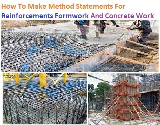
How To Make Method Statements For Reinforcements Formwork And Concrete Work
The Basic purpose of making the method statement is to explain the all step for performing the job and also explain which tools and materials standards must be used and fellow to complete the job. How To Make Method Statements For Reinforcements Formwork And Concrete Work. Method Statements For Reinforcements |Method Statements For Formwork |Method Statements For Concrete Work.
1. PURPOSE
-
How To Make Method Statement For Excavation And Backfilling
-
How To Repair The RCC Structures And How To Repair Leaks Roof
-
Basic Purpose To Use Spread Foundation/Footings
2. REFERENCE
3. RESPONSIBILITIES
3.1 PROJECT MANAGER
3.2CIVIL SUPERVISOR
3.3QC CIVIL INSPECTOR
3.4 SAFETY SUPERVISOR/OFFICERS
4. TOOLS
4.1 CARPENTER TOOLS
4.2 STEEL FIXER TOOLS
4.3 MASON TOOLS
5. PROCEDURES
5.1SITE PREPARATION
5.2FORMWORKS
5.3STEEL REINFORCEMENT
5.4CONCRETE POURING
5.5 CURING
5.6 REPAIRING
5.7COATING AND PROTECTION
5.8TESTING & INSPECTION
⦁ PURPOSE
This Method of Statement serves as a guideline in the implementation of concrete works (Formwork, steel Reinforcement, Concrete Pouring, Cast-in-place Concrete, Curing, Concrete Coating, and Protection) to be used.
REFERENCE
Criteria for Design and Construction of Concrete Structures
Concrete Foundations
Recommended practice for concrete Formworks
Standard Practice for Curing Concrete
Protective Coatings for Industrial Concrete Structures
Building Code Requirements for Structural Concrete
RESPONSIBILITIES
Project Manager
To ensure compliance by all parties to this procedure Quality Inspection Plans and other relevant Project Specifications and requirements.
Civil Supervisor
Ensure the correct IFC drawings, and approved procedures associated with the construction of concrete structures are available to, and used by, all personnel in charge of the work. Ensure that all submittals required by the client are duly approved and issued for use. Confirm construction materials are available and comply with the project specifications.
QC Civil Inspector
Check the construction work and ensure that all inspection and test requirements are identified; the documents are complete where necessary.
Safety Supervisor/Officers
Ensure the relevant Safety Procedures/Precautions are in operation and work permits have been obtained. Barriers and warning signs are posted where necessary.
TOOLS
CARPENTER WORK TOOLS
-
Calculate The Numbers of Items for The Stair Case
-
Load Calculation For Column Beam And Slab Design Calculation
-
What Is The Septic Tank|Tank Working Of A Storage Tank
Claw Hammer
Tape Measures
Pencil
Chisel
Block Plane
Clamp
Hand Saw
Workbench
Ruler, Level
Power Drill
Jigsaw
Circular Saw
Sander
Table Saw
Bench Grinder
Nailer
STEEL FIXER TOOLS
Chisel
Hammer
Bar tying hook
Bending lever, 12mm, 16mm, 20mm
Gauge measure (SWG)
Hack saw blade with frame
Spirit level
Plumb bob
Measuring tape
Rebar cutting machine
Rebar bending machine
MASON TOOLS
Trowel
Brick trowel
Small-size brick trowel
Gauging trowel
Angle trowel
Wooden float
Metal float
Plumb Bob
Right Angled Scales
Line Dori
Measuring Tape
Shovel
Bucket
Drum
Garden Shovel
Spirit level
Brushes
PROCEDURES

Site Preparation
- Select fill material shall be used for the bottom elevation of foundations, spread footings, or slabs-on-grade when fill is required to achieve the final grade.
- Cohesive fill material shall be used.
- The foundation shall not be placed above underground piping, telecommunication, or electrical items in a manner
- Required Compaction under the foundation
Formworks
- The form shall be substantial and sufficiently tight to prevent of mortar from the concrete.
- Forms and their supports shall be designed so as not to damage previously placed structures.
- Forms shall be properly braced or tied together to maintain position and shape.
- Forms shall be built to resist the pressures to which they will be subjected and to limit deflection to a practicable minimum within the specified tolerance.
- Reused forms to ensure that they have not become damaged, distorted, disassembled, or otherwise unable to perform as designed
- The size of forms ties and clamps shall be as specified in the IFC drawing.
- Forms shall be thoroughly cleaned of all dirt, mortar, and foreign matter and coated with a released agent before each use.
Steel Reinforcement
- Should be conducted inspected and checked before the reinforcing steel is placed.
- Reinforcing steel bars shall conform, to hot-rolled, high-tensile, deformed steel. These bars shall be acceptable.
- Coated reinforcing steel bars shall be used fusion-bonded Epoxy coated.
- The manufacture, fabrication, handling, placement, and storage of reinforcement shall be in accordance with the required standards.
- Handling and fabrication of the Epoxy coated reinforcement shall be in accordance with the required standards.
- Table 2 defines the minimum concrete cover measured from the outermost rebar (tie bar), that shall be provided for the reinforcement of cast-in-place concrete structures.
-
Why Using The Crank Bar In Slab Column RCC Beam
-
How To Calculate The Main Bar And Distribution Bar
-
Minimum And Maximum Percentage Of Steel In Column Beam Slab And Foundation
Minimum Concrete Cover Required
Concrete Structure Minimum Cover (mm)
Concrete cast against or permanently exposed to earth(including foundations over a sub-slab) 75
Formed concrete exposed to earth or weather
Supporting Process Equipment such as concrete pedestals for pipe rack support, pipe sleepers, or supports for horizontal vessels
Buildings, walkway platforms, stairs, AC pads 75 and 50
Concrete not exposed to weather nor in contact with the ground (which can be inspected from all sides):
Beams, columns, Slabs, walls, joists 5 and 25
Concrete exposed to seawater, raw water, or sewage 75
Between reinforcement and anchor flange/pipe within pipeline anchor blocks 100
Concrete slab over 50 mm sub-slab 50
Sidewalks, walkways, etc. 50
All sleeves, inserts, anchor bolts, water stops and other embedded items shall be installed in accordance with the design drawings and supported against displacement.
Reinforcing steel bars, anchor bolts or other steel embedments shall not be used as the means for grounding electrical equipment and shall not be tied to grounding neutral conductors, or any part of the lightning protection system.
Conduits, pipes, and other items made from aluminum shall not be embedded in structural concrete unless effectively coated to prevent an aluminum-concrete reaction.
Concrete Pouring
Conveying
Concrete should be placed so as to avoid segregation of the materials. Normally, concrete pumps are used to convey concrete where it is inaccessible. A stand-by concrete pump should be provided during the concrete pour.
When placement operation would involve dropping the concrete more than one (1) meter, the concrete mix should be deposited on a chute to avoid segregation of cement and aggregates.
Compacting or Vibrating
Concrete deposited on forms shall be thoroughly compacted or vibrated. Use the right vibrator to compact the concrete internally and externally. The use of metal rod could be instituted to attain maximum compaction of the concrete mix.
Curing
Structural concrete shall be continuously water cured in accordance with recommendations of ACI 305R, ACI 308, and as modified below. To avoid self-desiccation of the concrete mix, only a water curing method shall be used to cure the structural concrete.
Maximum total dissolved solids in water used for curing shall not exceed 1000 parts per million.
Water curing shall be continuous until the compressive strength has reached 70% of the specified strength,
The saturated burlaps shall be covered with a plasticized sheet vapor barrier, a minimum of 0.15 mm (6 mils) in thickness, and shall be kept in contact with the concrete surface at all times.
⦁ The essential steps of concrete repair.
⦁ Determine the causes of damage.
⦁ Evaluate the extent of the damage.
⦁ Evaluate the need to repair.
⦁ Select the repair method and material.
⦁ Prepare the existing concrete for repair.
⦁ Implement the repair method.
⦁ Cure the repaired area properly
Coating and Protection
- All concrete surfaces in direct contact with the earth shall be coated with two coats of coal tar or bitumen coating that conforms to The coating and shall be compatible with the curing compounds.
- Coating of above-ground/atmospheric concrete structures is not required unless otherwise specified in other standards and project documents.
- For above-ground use for chalking resistance and color retention (if required)
- A plasticized sheet vapor barrier, a minimum of 0.15 mm (6 mils) in thickness, or a 50 mm sub-slab (lean concrete) shall be placed beneath concrete foundations.
- shall not be used where the soil is contaminated with hydrocarbons and a compatibility test shall be conducted when the concrete surface is cured with an acrylic-based curing compound.
- compatibility test shall be conducted when the concrete surface is cured with a bitumen-based curing compound.
Testing & Inspection
- The contractor shall employ an independent approved testing agency to perform field and laboratory testing which shall include compressive tests of molded concrete cylinders, tests for slump, unit weight, air content (where air entrainment is required), and fresh concrete temperature. All testing shall be required standard.
- Testing Procedure will follow as per pre-approve of 3rd party Laboratory/ technician.
- A test procedure based on 3rd party Testing agency representative and also contractor representative witness inspection as required.
Read More
-
Calculate the Bar Bending Schedule For Retaining Wall
-
Find The Bar Bending Schedule For Plinth Beam
-
Calculate The Bar Bending Schedule For One Way And Two Way Slab
-
Bar Bending Schedule for The Pipe Sleeper
-
Calculate The Cutting Length of Chairs Bar
-
Bar Bending Schedule For The Staircase


One Comment