B.M And S.F Diagram Simply Supported Beam with Three Points Load
B.M And S.F Diagram Simply Supported Beam |Simply Supported Beam Three Points Load
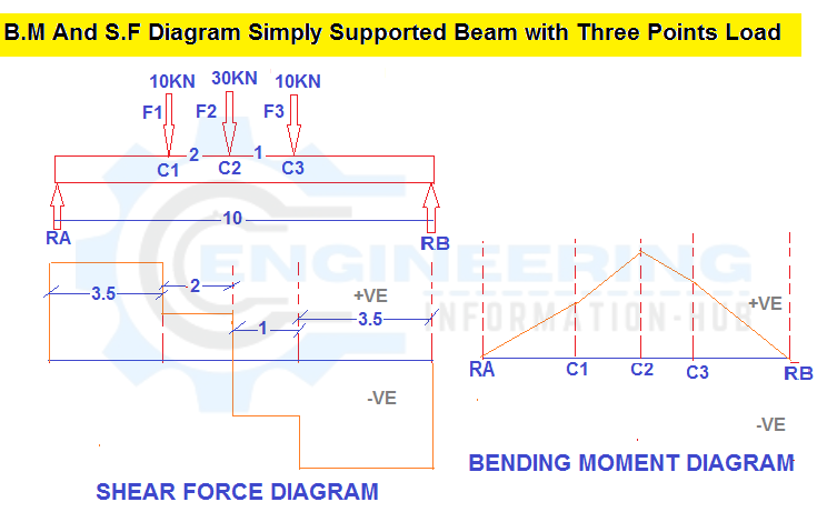
B.M And S.F Diagram Simply Supported Beam with Three Points Load
Today I will discuss the topic of bending moment and shear force. what is the bending moment | What is the Shear Force |B.M And S.F Diagram Simply Supported Beam with Three Points Load| B.M And S.F Diagram Simply Supported Beam |Simply Supported Beam Three Points Load.
What is the bending moment?
the bending moment may be a force commonly measured during a force x length (e.g. kNm). Bending moments occur once a force is applied at a given distance off from a degree of reference; inflicting a bending result. within the simplest terms, a bending moment is essentially a force that causes one thing to bend. If the thing isn’t well-restrained the bending force can cause the thing to rotate for a few sure purposes. it would even be value noting you’ll experiment and check out our free calculator to calculate the shear and bending moment diagrams of a beam.
What is the Shear Force?
Shear force is the force performing on a substance in a direction perpendicular to the extension of the substance, acting in a direction to a flat cross-section of a body.
Shear force is that the summation of the result of shear stress over a surface and infrequently leads to shear strain. Bending moment and shear force calculations ar essential whereas planning any structural members
READ MORE
Bar Bending Schedule For RCC Beam
EXAMPLE
We have the one simply supported beam with the three-point load F1=10kN, F2=30kN, and F3=10kN. The distance between two Reaction Force and span =10m and distance between F1 to F2= 2m and F2 to F3=1m.calculte the bending moment and shear force diagram and calculate the Reaction of RA And R.B.
Given data
F1=C1=10KN
F2=C2=30KN
F3=C3=10KN
The span of the beam =10m
Solution
We know
The sum of upward force = The sum of downward force
R.A+R.B = F1+F2+F3
R.A+R.B = 10+30+10
R.A+R.B = 50KN———————- 01
Sum of bending moment at A = 0
R.B x 10-10×6.5-30×5.5-10×3.5=0
10R.B-65-165-35=0
10R.B=65+195+35
10R.B = 265
10 divided by both sides for calculate the value the Rb
10R.B= 265/10
R.B = 26.5 KN
From equation 01
R.A+R.B = 50KN
R.A+26.5 =50
R.A= 50-26.5
R.A = 23.5 KN
Now Fist we calculate the shear force
SFB = -26.5 KN
SFc3 = -26.5+10 = -16.5KN
SFc2 = -16.5+30 = 13.5 KN
SFc1 = 13.5+10 = 23.5KN
SFA= 23.5 KN
Now we calculate the bending moment
BM.b = 0 KN.M
BM.C3 = RB X distance (from RB to C3)
BM.C3 = 26.5 x 3.5 = 92.75KN.M
BM.C2 = RB X distance RB to C2 – F3 X distance F3 to C2
BM.C2 =26.5 X 4.5 -10 X 1= 119.25 – 109.25= KN.M
BM.C1 = RB X distance RB to C1– F3 X distance F3 to C1- F2 X distance F2 to C1
BM.C1 =26.5 X 6.5 – 10 X 3 – 30 X 2 = 159 – 30 – 60 = 69 KN.M
BM.A = RB X distance RB to A– F3 X distance F3 to A- F2 X distance F2 to A –F1 X distance F1 to Point A
BM.A = 26.5 X 10 – 10 X 6.5 – 30 X 5.5 – 10 X 3.5 = 265 – 65 -165 – 35= 0
other post
Why Using The Crank Bar In Slab Column RCC Beam
Load Calculation For Column Beam and Slab Design Calculation







One Comment