
How To Calculate The Volume of Concrete For Octagonal Foundation
What Is The Octagonal Foundation |Volume of Concrete For Octagonal Foundation

How To Calculate The Volume of Concrete For Octagonal Foundation
In this, I will explain what is the octagonal foundation and how to calculate the volume of concrete for the octagonal foundation. An octagonal foundation which foundation has eight sides with all sides equal corners or eight angles inside all angles is called an octagonal foundation. octagonal foundation or footing is used in a vertical column, drum, vessel, Tank, etc. What Is The Octagonal Foundation |Volume of Concrete For Octagonal Foundation
Architecture
. What Is The Octagonal Foundation |Volume of Concrete For Octagonal Foundation
What Is The Octagonal Foundation
The definition of the octagonal foundation which foundation has eight sides all sides equal corners or eight angles inside all angles equal is called an octagonal foundation. octagonal foundation or footing is used in a vertical column, drum, vessel, Tank, etc.
Architecture
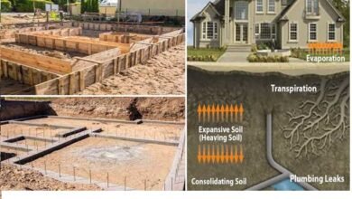
In architecture, the octagonal foundation might refer to a building or structure whose base is shaped like an octagon. Octagonal foundations were common in historical architecture, especially in churches and fortifications.
Engineering
In civil engineering, an octagonal foundation could be a type of footing or base used to support a structure. The octagonal shape could provide stability and distribute the weight of the building evenly.
Symbolism
In symbolic or mystical contexts, the octagonal foundation might represent various ideas depending on cultural or religious beliefs. For example, in some belief systems, the octagon symbolizes balance, regeneration, or the union of opposites.

How To Calculate The Volume of Concrete For Octagonal Foundation
Now we calculate the volume of concrete for an octagonal foundation with an example.
Related Post
Calculate The Volume Of The Cement Sand And Aggregate
Calculate The Volume Of The Cement Sand And Aggregate
Calculate The Quantity Of The Bricks Cement And sand In One Cubic Meter
Example
Given data
length of the octagonal foundation side = S= 1200mm = 1.2m
Height of the octagonal foundation = H= 3000mm = 3m
we calculate the volume of the octagonal foundation first we calculate the area and then we calculate the volume.
Formula of octagonal foundation
Area of the octagonal foundation =A = 2(1+√2)s²
A =area of octagonal foundation
S = side of octagonal foundation
The volume of the octagonal foundation = A x h
Now we put the given value in this formula
A = 2 (1+√2)s²
A = 2 (1 + √2) 1.2²
A = 6.952m²
The volume of the octagonal foundation Concrete = A x H
The volume of the octagonal foundation Concrete = 6.952 x 3
The volume of the octagonal foundation Concrete = 20.857m³
Read More
Benefits of Insurance in Civil Engineering
Design The heavy-load RCC Column
Why Using The Crank Bar In Slab Column RCC Beam
Thanks For Reading The Article Get More Information And Share it With Others
JOIN US & LIKE MY OFFICIAL FACEBOOK PAGE


One Comment