Pre Stress Double Tee Design Calculation
Pre Stress Double Tee Design Calculation
Today I have a topic about double Tee design calculation |Pre Stress Double Tee Design Calculation.
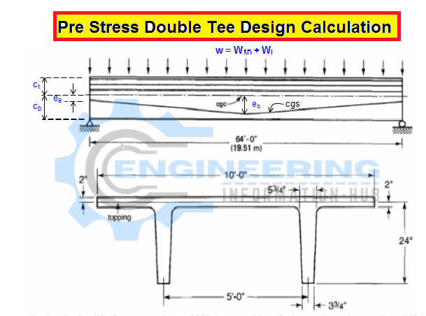
A pre-tensioned merely supported 10LGT24 double T-beam while not topping, it’s subjected to an identical superimposed gravity dead-load intensity Wsp and burden W₁.

W=420lb/ft w=Wsd+Wι
fρ¡=189000 psi fρ¡≈0.70fpu
fρe=150000psi
Determine the intense fiber stresses at the midspan because of two
1.1- The initial full prestress and no external gravity load
1.2- the ultimate service load conditions once prestress losses have taken place
Allowable stress
fc = 6000 psi concrete cylindrical strength
fo=270000 psi
fpy= 220000 psi
fpe= 150000 psi
ft = 12√f’c foot = 930 psi most allowable lastingness at the time of initial stress in conc.
fci = 4800 psi conc. compressive strength at the time of initial prestress
fci= 2880 psi fci= zero.6f’ci most allowable stress in concrete at initial prestress
fc = 2700 psi fc=0.45f’c most allowable compressive stress in concrete at service.
n = ten nos 7- wire strand tendons with a 108-Di strand pattern area unit wont to prestress beam
d=12.70 millimetre military intelligence of tendons
d = 0.50 in
Section Properties
L=64 ft
Ay = 1623.7 sq.inch y = two.00 neutral axis
A=689sq.inch At=240 tension space
Ac =449sq.inch ec=14.77 inch
lc=22469 inch4 ee=7.77inch
r²=5004sq.inch = lc/ac Sb=126inch³
Cb=17.77inch St=3607inch³
Ct=6.23inch Wd=359lb/ft
122489 inf
Initial Conditions at Prestressing
A = 1.53 sq.inch
Pi=289170 pound
Pe = 229500 pound
Maximum moment at mid-span
Md= 2205696 inch-lb
M= wl²/8
ft = Pi/Ac(1+ec/r²)+Md/Sb foot= Pi/Ac(1+ec/r²)-Mt/St
f’=-70psi
Fb=Pi/Ac(1+ec/r²)+Md/Sb fb= Pi/Ac(1+ec/r²)-Mt/Sb
fb= -2277 psi
fb 2277 psi < 2880psi allowed.
2. Final condition at Service Load, Basic methodology.
Midspan moment because of superimposed dead and loading has
M= 2580480 inch-lb Msd+Ml=Wl²/8
Mt= 4786176 inch-lb
f’ = -898 psi ft=pe/Ac(1-ec/r²)-Mr/St
f’=-898psi < fc=0.45f’c 2700psi
fb= 594psi T fb=-pe/Ac(1+ecb/r²)+Mt/Sb
fb=594psi < ft=12√f’c 930psi
3. Final service load condition by the line-of-thrust, C-Line methodology.
Since
Pe =229500 pound
Mt= 4786176 inch-lb
a = 20.85 inch a=Pe/Mt
e’=6.08inch e’=a-ec
f’=-898psi ft= pe/Ac(1-e’ct/r²)
fb=592 T fb=-pe/Ac(1-e’ct/r²)
4. Final service load condition when losses victimization the Load-Balancing methodology
At middle spen
Pt= Pe= 229500 pound
a=ec= 14.77 inch
For balance load
W₂ = 552 lb/ft
Thus, if the whole gravity load would are 552 lb/ft solely the axial load P’/A would act as if the beam had a parabolically drooped sinew with no eccentricity at the supports. this can be a result of the gravity load being balanced by the sinew at the mid-span. therefore
Total load w/c beam = 779 lb/ft Wd + (WED + WL)
Unbalanced load, Wub = 227 lb/ft
unbalanced moment Mub= 1394688 inch-lb.
f= -898 psi C ft=Pt/Ac-Mub/St
fb = 592 psi T fb= PtAc+Mub/Sb
fb=592 psi < 930 psi enable
Learn More
Bar Bending Schedule For Pipe Sleeper
Difference B/w Flexible and Rigid Pavements
Thanks for Reading Article Get more Information and share it with others.
JOIN US & LIKE MY OFFICIAL FACEBOOK PAGE


